Reading and decoding DCC packets with a low-cost USB logic analyzer.
This post started as a quick note, but the topic deserves more context.
In the video below, I walk through how DCC packets look on the wire and how you can decode them with a simple USB logic analyzer. If you are moving from analog model rail control to digital, this is one of the easiest ways to understand what your command station is actually sending.
What this video covers
- Capturing the track signal with a low-cost logic analyzer
- Looking at the waveform in a logic analyzer tool
- Identifying packet boundaries
- Interpreting bytes using the NMRA DCC format
- Verifying checksum behavior to confirm packet integrity
Quick DCC packet refresher
At a high level, a standard DCC packet is made of:
- A preamble (a stream of
1bits) used for synchronization - One or more data bytes (address + command/instruction bytes)
- An error-detection byte (XOR checksum)
- A packet end bit
When you see this structure in a capture, DCC becomes much less mysterious. The protocol is very structured, and once you can spot the repeating pattern, troubleshooting decoders and command behavior gets easier.
Why a logic analyzer helps
A logic analyzer gives you objective visibility. Instead of guessing whether a command was sent correctly, you can inspect the exact bit stream and compare it against the NMRA expectations.
This is useful for:
- decoder troubleshooting
- custom electronics projects
- validating command station output
- learning how DCC actually works under the hood
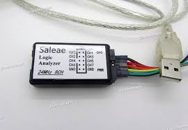
Hardware used
I used a low-cost USB logic analyzer, which is enough for this kind of packet inspection.
If this kind of deep-dive is useful, you can subscribe to my YouTube channel.
I also publish more model railroad videos in this playlist.